Hydraulic problem on a 2755
Allen Edwards is an expert on John Deere tractors. He's worked hands on with them for more than 30 years. In this video he explains the basics of how the hy.
2040 hydraulics
John Deere Hydraulic System Diagram - cloudshareinfo. John deere 7000 planter parts diagram Planter 1770 deere blower john hydraulic valve beyond power series hookup vacuum control parts row 777parts tractors dual systems spare Deere hydraulics troubleshooting spelling. John deere 7000 and 7100 planter
Q&A John Deere 4020 Hydraulic System Diagrams & Parts JustAnswer

Winch. The diagram shows a winch powered by a hydraulic motor. The directional control valve with built-in relief features optional flow control to control the speed of the winch . The hydraulic pump and motor must be matched to the torque requirements of the winch.
John Deere Hydraulic System Q&A, Diagrams & Parts JustAnswer

John Deere Lawn & Grounds Care Division 4200, 4300 and 4400 Compact Utility Tractors. • System Schematic • Theory of Operation • Troubleshooting Chart • Diagnostics • Tests & Adjustments. bearings, hydraulic seals, fuel injection pumps or other sensitive parts and components may cause product malfunctions. Reduce
Schematic Hydraulic System The Wiring Diagram

7. Quadrant. John Deere's hydraulic system diagram illustrates the components of the system, including a lever with a knob, push nut, and insert. This combination allows for precise control of the tractor by providing operators with easy access to simple and effective adjustments.
John Deere Hydraulic System Diagram cloudshareinfo

The John Deere 2040 is a sturdy, reliable tractor that is widely used in farming and agricultural operations. One important component of this tractor is its hydraulic system. The hydraulic system of the John Deere 2040 is responsible for providing power and control to various implements and attachments. Understanding the hydraulic system.
John Deere 318 Hydraulic System Diagram diagramwirings

John Deere Lawn & Grounds Care Division F911, F915, F925, F932 and F935 Front Mowers Serial No. (010001— ). Group 10—Hydraulic Lift Cylinders Group 15—Weight Transfer Valve Group 20—Oil Cooler. Group 20—System Schematic Diagram
[Get 45+] Hydraulic Schematic John Deere Hydraulic System Diagram

The John Deere 4440 is a versatile tractor that is equipped with a robust hydraulic system. This system plays a crucial role in operating various implements and attachments, making it an essential component for a range of agricultural tasks. One key feature of the John Deere 4440 hydraulic system is its high capacity.
Troy Bilt 13101 16HP GTX HYDRO GARDEN TRACTOR (S/N 131010100101) Parts Diagram for HYDRAULIC

Illustrated Factory Diagnostic and Repair Technical Manual for John Deere Tractors 5200, 5300, 5400 and 5500 This manual contains high quality images, circuit diagrams, instructions to help you to operate, maintenance, diagnostic, and repair your truc / Deere Technical Manuals. Tests and Adjustments Hydraulic System Operation,.
John Deere Hydraulic System Diagram cloudshareinfo
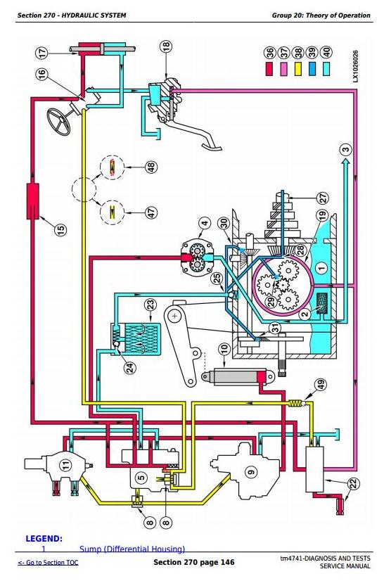
The hydraulic system diagram of a John Deere tractor illustrates the intricate network of hoses, valves, and cylinders that make up the hydraulic system. It shows how hydraulic fluid is circulated, pumped, and controlled to provide the desired hydraulic power to different parts of the tractor.
[DIAGRAM] John Deere Hydraulic System Diagram

The implement control levers are likely the early design similar to what was used on the early 318 with 4 port power steering. Of course the 300 and the 316K don't have any power steering. Below is the hydraulic schematic for the early 318 -- note that the right valve has a float detent built in. The rock-shaft control on the left does not.
[Solved!] John Deere Hydraulic System Diagram in 2023

John Deere 318 User Manual • Legend for hydraulic system schematic—early 318 • John Deere Gardening equipment. Manuals Directory ManualsDir.com - online owner manuals library. Search. Directory. Brands.. LEGEND FOR HYDRAULIC SYSTEM SCHEMATIC—EARLY 318. 1—Hydrostatic Transmission. 10—Variable Hydrostatic. 17—Steering Valve (4.
John Deere 2755 Hydraulic System Q&A on Problems, Diagrams & Parts JustAnswer

Hydraulic System Leaks To locate a leak, use appropriate means. Protect body and hands from liquid under pressure. Any liquid under pressure (particularly oil from hydraulics) can penetrate the skin and cause. JOHN DEERE 8010 SERIES 8010 / 8410 8010T / 8410T 8020 SERIES 8020 / 8220 / 8320 / 8330 / 8420 / 8520 8020T / 8420T / 8520T 8030 SERIES
[View 27+] Hydraulic Schematic John Deere Hydraulic System Diagram
All relief valves described below operate in the same way. The early model *850 and 950 tractor has one relief valve located in the rockshaft piston cover. If hydraulic oil pressure exceeds 12756-13445 kPa (128-134 bar) (1850-1950 psi), the valve opens and relieves oil to sump. Late model * *850 and 950 tractors have two relief valves.
John Deere 4430 Hydraulic Diagram Wiring Diagram
John Deere Worldwide Commercial and Consumer Equipment Division TM1630 (Apr01) Replaces TM1630 (1Feb98). • System Schematic • Theory of Operation • Troubleshooting Chart • Diagnostics • Tests & Adjustments. bearings, hydraulic seals, fuel injection pumps or other sensitive parts and components may cause product malfunctions. Reduce
John Deere 4430 Hydraulic Diagram Wiring Diagram

JOHN DEERE . Created Date: 9/28/2009 9:12:39 PM